Yesterday (Dec 9) Peter and I went up to ML to work on the following:
Remove Heliax cables – Together we were able to remove 29 cables that consisted of a mix of 9-m, 7-m, and 2-m lengths. The cables are stored in the support cone below the telescope and are separated by lengths. We believe we can complete the removal of the Heliax cables within the platform with 2 more days of work (requires two persons).
Repair right rear exist frame – When we arrived we noticed the metal structure holding the canopy down had broken away. It turn out that the two bolts holding it down were stripped (possibly wrong size to start?) so we replaced them with the correct size. Photo after repair shown here.
New hold down bolts, this one showing the left side.Photo of frame after replacing hold down bolts. The horizontal curved support structure that came loose is circled in blue.
Remove AC plugs for ROACH-2 chassis – When we arrived we found 2 of the 4 ROACH bays were powered up unintentionally via the WTI network power switch, probably as a result of a power failure recovery routine. In order to prevent this from happening in the future we removed the AC power plugs to the rear of all 32 ROACH-2 units. We left the WTI units powered on so that we can perform remote reboots of network switches and other accessories.
Photo of on of the four ROACH-2 bays with WTI Network Power Switch at top.
Pull long extension cord from Eaton UPS to Control Container – Being that we will no longer power up the ROACH-2 hardware, we decided to use the large Eaton UPS, model 9170+, to power the PCs and other accessories within the Control Container.
Eaton 9170+ UPSYellow power cord carrying UPS power into Control Container.
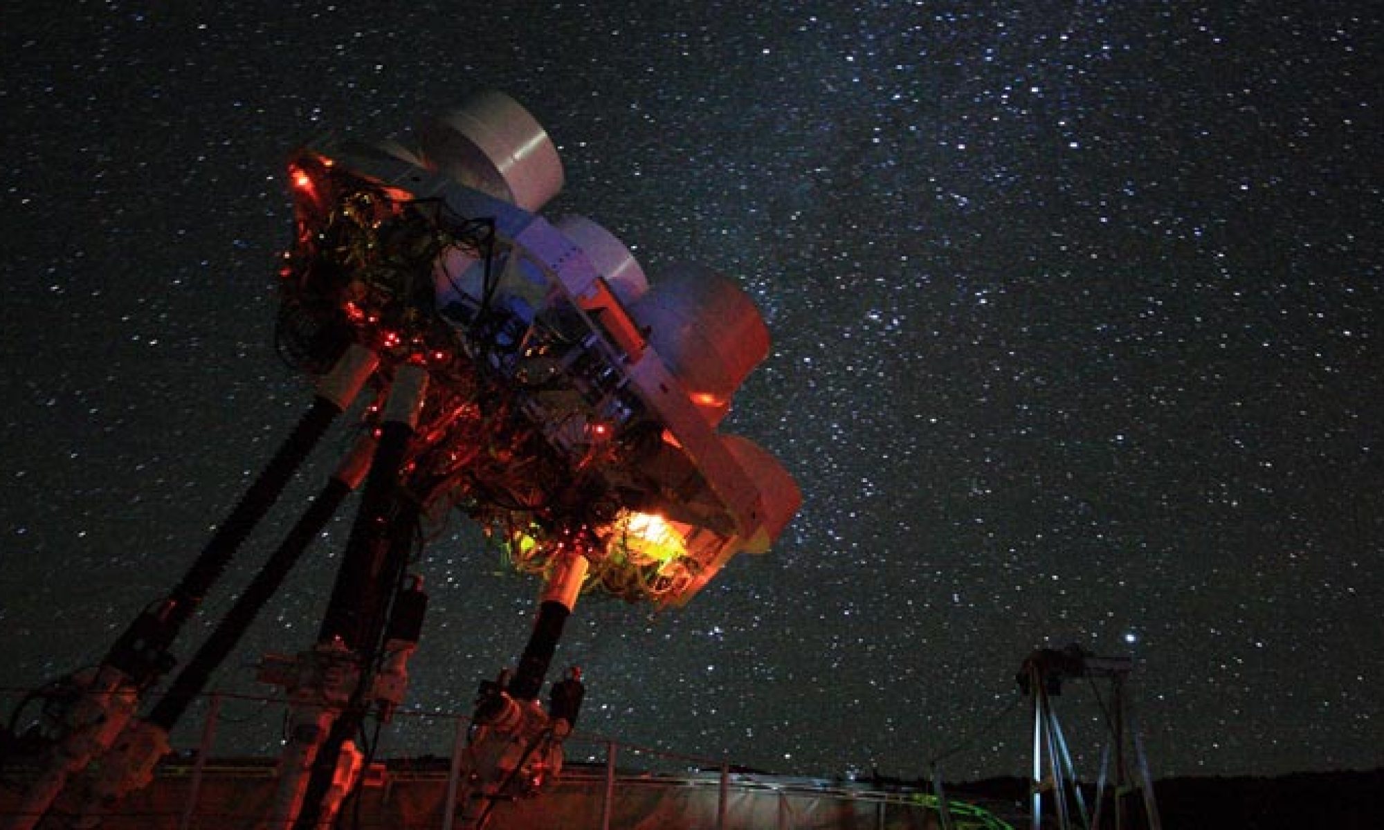
I’ve attached the 6 views of the telescope as it stands today. There is still much to do but hopefully with the stiff Heliax cables out of the way things will go a bit faster.
Peter and I came up with this preliminary plan to remove items from the telescope. Please take a look when you have a chance and either comment below or edit the file directly. I’ve added some recent photos of the telescope for reference.
Telescope stowedTelescope extendedView of platformView of bottom of platform
Adam, Peter, and I worked on painting the second dish yesterday and below are some before and after photos. According to Peter this particular dish has been on the platform (Rx2) for around 2 years.
Primary after cleaning with isopropanol alcohol in preparation for painting.
A close inspection of the lower right portion of the dish is shown below. Note that the surface is severely cracked and the metallic coating appears to be worn or oxidized to the point where I can see a few millimeters into the translucent epoxy material.
Closeup of a portion of the primary.Adam spraying the dish. We applied a total of 4 coats of metallic paint.Light sanding with 600 grit paper after waiting 24 hours to cure.Dish surface after sanding.Closeup of the dish surface after sanding. I can definitely feel the raised surfaces of some of the cracked areas.DC resistance measurements show less than 1 Ohm throughout the dish. The resistance across the entire dish (edge to edge) measured slightly over 1 Ohm.Secondary after preparation for painting. Note the unusual dark gray color. DC resistance measurements were in the 10-100 kOhm range.Secondary after 4 layers of paint but before sanding.DC resistance measurements after sanding. Values were quite low at around 0.3 Ohms for multiple measurements.
Peter and Adam plan to take up the primary and secondary assemblies to Maunaloa on Monday and will proceed with assembly and installation onto the platform.
Following my last progress report, I have collected our earlier optical pointing data since 2017. These are 250-star all-sky pointing data. Location of some OTs changed a few times in the past:
OT3_OT3
2017–now (unchanged): between Ant3/Ant4, r=0.606m
OT4_10054118
2017–now (unchanged): between Ant5/Ant6, r=0.606m
unplugged after 2019/Mar/20
ST-i_12232
2017–now (unchanged): between Ant1/Ant2, r=0.606m
ST-i_12234
2018/Feb/26–now: Ant3 (r=1.400m)
ST-i_12239
2018/Apr/11–2019/Aug/20: Ant2 (r=1.400m)
ST-i_12244
2019/Apr/3–now: Ant6 (r=1.400m)
ST-i_12705
2020/Aug/21–now: Ant2 (r=1.400m)
In other words, OT for Ant2 went from 12244 to 12239 and then to 12705. After the repair, 12244 went to Ant6 instead.
For the most part of the data, the OT configuration is the same as the one shown in the previous report.
Median pointing offsets
The first step is to check if all the data sets (of the same OT) can conform to a mean or median pointing offset pattern. After removing data sets that are incomplete, or ones that had incorrect PTC correction mode, it turns out the median pointing offset fairly describes a large fraction of the data. The RMS residual from the median can be as small as 0.05 arcmin for OT3/OT4 (about 1-pixel accuracy) and 0.2 arcmin for ST-i (about 1-pixel accuracy). The median pointing offset and the residuals are shown below:
Median pointing offsets
Residuals:
ST-i_12244 is a bit peculiar. It seems to be unstable. I also had some trouble when I tried to identify where the platform rotation axis is in relation to this OT. I will leave it out of the next analysis for clarity.
Double-saddle model parameters
Using the median pointing offsets, I can solve the model parameters from the difference between pairs of OT. Similar to the previous report, the dX and dY offsets are treated independently and can return two sets of parameters from the same measurement. I plan to rectify this in future analysis. The current results can be summarized below:
The first plot shows the amplitude of the primary saddle (A1, blue) and the secondary saddle (A2, orange) derived from dX (solid lines) and dY (dashed lines) as a function elevation, for each pair of OTs. The second plot shows the corresponding position angles (phi1 and phi2) of the two saddles. Also shown on the plots are the currently adopted model parameters (victor10v2) shown in green (A1/p1) and yellow (A2/p2). In Victor’s analysis, the position angles (p1 and p2) scattered around zero and are set to zero by choice.
Note that if the OTs all tilt according to the same double-saddle model, all pairs are supposed to return the same parameters. It is clearly not the case here. Parameters from dX and dY also do not agree with each other very well.
We can, however, see that pairs between three OTs (OT3, ST-i_12232, OT4_10054118) return more consistent amplitudes (A1, A2) than most. These are the three OTs installed in the platform directly, at a distance of 0.6m from the center, separated by 120deg with each other. They also agree very well with Victor’s results from 2010. The position angles are a bit hard to interpret, but I will try to do a joint fitting from the three OTs. This hinted that OT mounted on the antenna baffles may be subjected to additional tilting beyond what was predicted by the double-saddle pattern.
Summary
Optical pointing offsets have been very stable for most OTs (except for ST-i_12244). A set of median pointing offsets can be constructed from pointing data since 2017.
Using the difference of these median offsets, we can derive the deformation model parameters from five good OTs.
Three OTs (OT3, OT4, 12232) installed directly on the platform show self-consistent results. The parameters derived from these three also agree with what Victor obtained in 2010 (with OT3 and OT4). The new parameters derived from the median offsets seem to have smoother dependence on elevation due to better sampling.
I will try to do a joint fitting from the three platform-mounted OTs to derive a single set of parameters. As for the antenna-mounted OTs, we will probably need to introduce additional terms to the tilt model (e.g. a tilt in the dEl / vertical direction).